DEFINITION
Sheet metals are generally classified as metal sheets that have a thickness ranging from 0.4 mm to 6 mm. Different metals such as Steel, Aluminum, Copper, Brass, Nickel, Titanium can be made into sheets by rolling process. Sheet metals are widely used in industries such as aerospace, automotive, electronic appliance, construction, etc.
DESIGN METHODOLOGY
For making a sheet metal component following steps are performed:
The selection of materials depends on the application, formability, weldability, corrosion resistance, strength, weight, and cost. The thickness of the sheet is decided on the requirements of strength. A detailed comparison can be made using the available design data handbooks with different material specifications.
Below are the factors designer needs to consider while modeling a sheet metal component.
- Wall Thickness:
- Bend Radii:
- Orientation of Holes & Slots:
- K Factor:
- Bend Allowance:
- Bend Deduction:
- Bend Reliefs:
- Some Additional Features:
- Hems are folds at the end of a part to create a rounded edge and it is recommended to have the minimum inside diameter is same as the material thickness and the hem return length should be minimum four times the sheet thickness.
- Notches must be at least same as the sheet metal thickness or 0.04" (1mm), whichever is greater and can be no longer than 5 times its width.
- Tabs must be at least 2 times the sheets metal thickness or 0.126” (3.2mm), whichever is greater and can be no longer than 5 times its width.
- Curls dimension outside radius must be at least twice the material’s thickness.
- When Sheet metal parts have sharp corners, try designing a fillet half of the material thickness.
- Countersinks must be separated from each other by a distance of at least 8 x sheet metal thickness, 4 x sheet metal thickness from an edge and 3 x sheet metal thickness from a bend.
While designing any geometry, it is always a good idea to maintain uniform wall thickness throughout the body. Geometry with more than one wall thickness requires sheets of different thicknesses, which requires reorientation and alignment of parts that consume time. Parts with different thicknesses will have different bend parameters which may result in the inaccuracy of the desired shape.
To avoid any fractures or distortions, it is necessary to keep inside bend radius at least equal to sheets thickness. The bend radii should be maintained consistently throughout the part as keeping the same bend radii across all bends makes the part cost effective. Whenever making a bend, it is always preferred to make bends in a single plane as this will avoid any additional reorientation while manufacturing that part.
Keep holes and slots diameter at least as large as sheet metal thickness. Holes diameter less than the sheet metal thickness results in higher punch loading, longer burnish in the holes and excessive burr. If the hole gets too close to an edge a bulge can appear near an edge. Spacing between holes should be at least two times the sheet metal thickness.
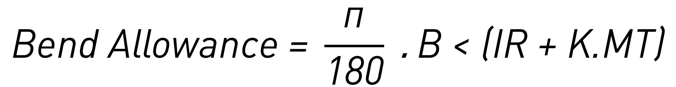
The K Factor in sheet metal working is the ratio of the neutral axis to the material thickness. K Factor changes its value with respect to physical properties and thickness of materials. Generic values for K Factor varies from 0.3 to 0.5.
The Bend Allowance is defined as the material to add to the actual leg lengths of the part to develop a flat pattern. When the sheet metal is put through the process of bending the metal around, the bend is deformed and stretched. This elongation can be calculated from the below formula of which Bend Allowance is a function of Material Thickness (MT), the Bend Angle (B<), the Inside Radius (IR), and the K Factor (K):
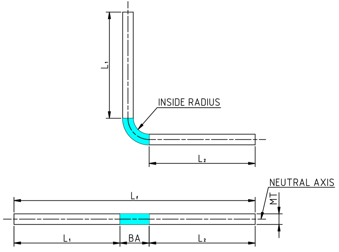
Figure 1: Bend Allowance
To find the total flatten length, we can use the formula given below:
Lf = L1 + L2 + BA
Where, Lf = flatten length, L1 = Flange length after bend of side 1, L2 = Flange length after bend of side 2, BA = Bending Allowance
You can also use the above formula to back calculate the exact value of K factor by measuring the flat length (Lf) and then bending it to a known bend angle (B<), inside radius (IR) and measuring flange length L1 and L2. This data can then be inserted in the bend allowance equation to calculate the K factor for your specific material and thickness.
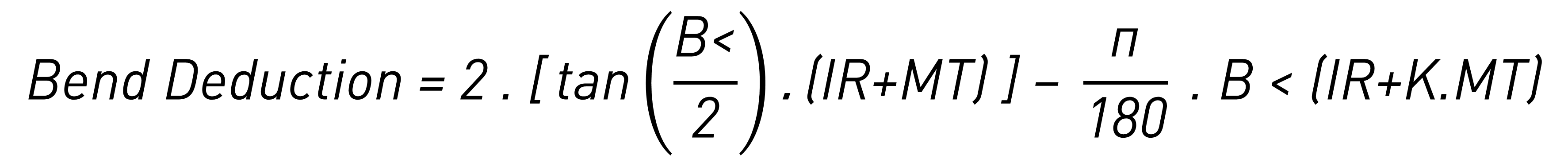
The Bend Deduction is defined as the material that needs to to be removed from the total length of your flanges to arrive at the flat pattern. When trying to develop a flat pattern, the deduction has to be subtracted to get its overall length as show in the below image. The Bend deduction can be calculated using the below equation.
Where, Sheet Metal Thickness (MT), Bend Angle (B<), Inside Radius (IR), KFactor (K)
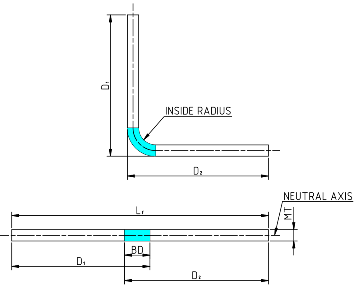
Figure 2: Bend Deduction
Also, the below equation can then be used to determine the flat pattern length.
Lf = D1 + D2 + BD
Where, Lf = Flatten length, D1 = Flange length with bend side 1, D2 = Flange length with bend side 2, BD = Bending Deduction
Bend reliefs are implemented where a bend extends on an edge. The relief notches are added to prevent tearing and easy bending of the part. Relief helps to control unwanted the sheet metal deformation. Bend reliefs should be at least same as the thickness of sheet metal in terms of width and should be equal to or greater than inside bend radius in terms of depth. Bend reliefs can be rectangular, tear and obround.
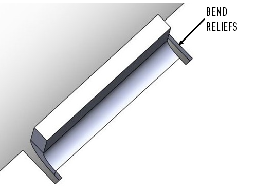
Figure 3: Bend Reliefs
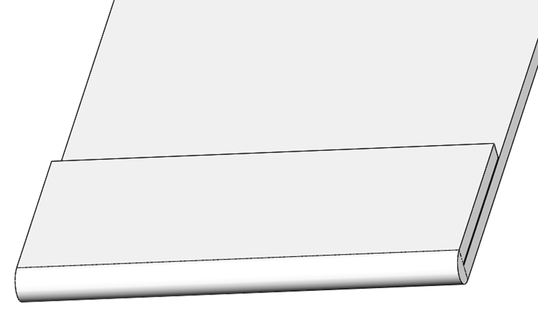
Figure 4: Hemming
After designing and completing a 3D model, drawings are created for manufacturing. Flat patterns are included in drawings to show bend lines. A bend table is included in the drawing that indicates the angle and direction of bend. Drawings includes all the information that is required for manufacturing such as surface finishing, coating, plating, etc. DXF or DWG file of a flat pattern is also created for manufacturing.
- Cutting:
- Laser Cutting: Laser is used for cutting the sheets. It can generally cut sheets up to 8mm thick but the speed of cutting varies from thickness to thickness. Laser cutting provides a precise cut with a tolerance of +/-0.005”.
- Water jet cutting: High-pressure water jet with abrasive particles is used to cut material. It can cut up to 150mm thick plates but the speed is less compared to Laser cutting. It also gives the same tolerance as Laser cutting but the surface finish varies depending on parameters.
- Mechanical shearing: To cut the metal sheet into shapes for mass production mechanical shearing is used. Mechanical shearing is a quicker process compared to laser cutting. A die and punch are used to shear the sheet into the required shapes.
- Bending:
- Drawing:
Bending is a metal forming process used to bend the sheet along a straight axis. This can be done by brake press machines using V-bend dies, goose-neck dies, U-bend dies, etc.
Drawing involves readily drawing of the sheet metal blank into a forming die with the help of a mechanical punch to obtain a hollow or curved surface. The forming limit of the sheet is considered while developing the component and it varies with materials and thicknesses.
Once the sheet metal model is formed, the corners or opened gaps/edges are welded to maintain the strength and geometry of the component. Welding methods that are generally used are TIG, MIG, spot welding, etc. For Aluminum and Brass parts, Brazing is used for joining. Besides welding, riveting can also be considered for joining.
The welded sheet metal component has to be surface finished to remove the sharp edges and to optimize the cosmetic appearance of the product. This can be achieved through Hand grinding, jitterbugging, wide belt sandpapers, buffing, sandblasting, priming and painting, powder coating, plating, etc.
PLATFORMS
CAD software offers extensive range of features that can be used for not only designing but also manufacturing sheet metal parts. Some of the commands that are available in CAD software are as follows:
- Standard gauge thickness that can be chosen based on your application.
- Base flange to draw the base of the sheet metal component.
- Edge flange to draw flange with bend angles and flange length.
- Lofted bends to connect two different open profiles.
- Hems, jogs, and curls to create curved or rolled surfaces near the edge.
- Breaking the corners with fillets or chamfers.
- Forming tools to create features like ribs, louvers, lances, embosses, and extruded flanges.
- Weld details to sheet metal parts on models or drawings.
- Flatten to generate flat patterns for manufacturing with bend compensation.
- Export flatten parts to manufacturing ready formats such as DXF.
ADVANTAGES
- With the use of CAD/CAM system and CNC technology the parts can be accurately manufactured with a fine tolerance of +/- 0.05mm
- Formability of material to get into the desired shape.
- Ease of availability of material at low cost.
LIMITATIONS
- Many parameters to consider while designing and manufacturing.
- The forming limit of sheet metal has to be considered while achieving the geometry and it varies with the thickness of the material.
- Generation of internal stress in the parts during loading and unloading.
- Springback behavior of pressformed parts.
- High tooling cost for initial phase.


